June 20, 2017
The Argo Tunnel (Figure 1) was the primary drainage and ore transport tunnel from Nevadaville to Idaho Springs. It was excavated from 1893 and 1910, drained water from several mine workings, and allowed ore carts to be wheeled right up to the Argo Mill next door. Although the tunnel has not been used to transport ore since the 1940s, water still drains through it constantly. The tunnel discharge averages 275 gallons of acidic contaminated water per minute. Approximately 850 pounds of dissolved metals are released from the tunnel each day. The Argo Tunnel Water Treatment Plant began operating in April 1998, treating water from the Argo Tunnel. Flows from the Big Five Tunnel at the west end of Idaho Springs and groundwater from Virginia Canyon were added in 2006 (Figure 2).
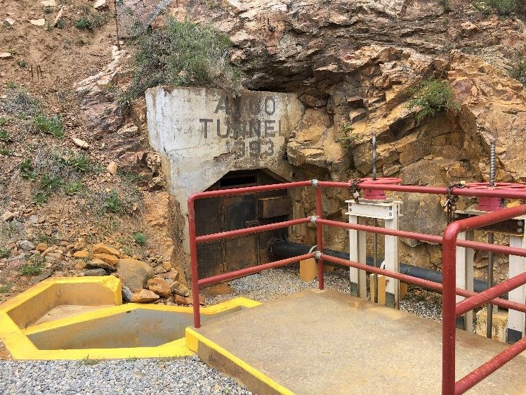

Figure1: Entrance to the Argo Tunnel Figure 2: Discharge from Virginia Canyon and Big
Five Tunnel
The Argo Tunnel Flow Control Bulkhead (Figure 3) was completed In August 2015 at a cost of approximately $970,000. A pipe runs through the concrete plug so water treatment plant operators can regulate the flow and control water levels inside the mine pool. The tunnel has a history of surge events that released untreated mine water into Clear Creek. The primary contaminants include acidity and a host of heavy metals, including aluminum, copper, iron, manganese and zinc.

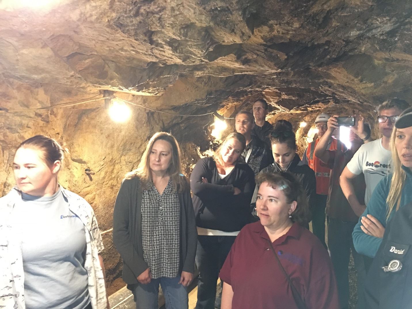
Figure 3: Bulkhead Figure 4: RMWQAA group inside the tunnel
After flowing down from the tunnel, the influent accumulates in an equilibration basin (Figure 5) before entering the plant. From there it is mixed with recycled metal hydroxides and hydrated lime until a pH of 9.9 S.U. is achieved. The lime system includes a silo for storage (Figure 6), a slurry mix tank in the enclosure along with the silo, piping from the lime enclosure to the WTP, a day tank within the WTP and diaphragm metering pumps for feeding the lime into the treatment process. Recent upgrades converted the plant’s conventional process to a high-density sludge (HDS) process. The HDS process sends metal hydroxides into a conditioning tank where they are coated with lime and sent back through the system for up to 30 additional treatment cycles. The process is more efficient at removing metals from the water, resulting in denser filter cake and less material sent to landfills.
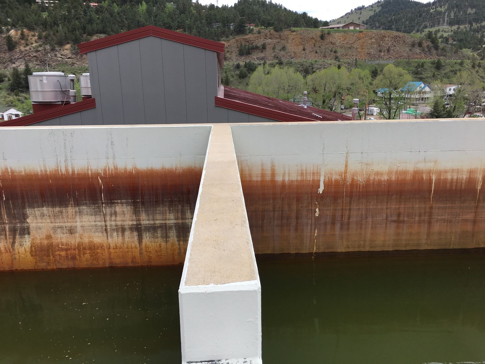
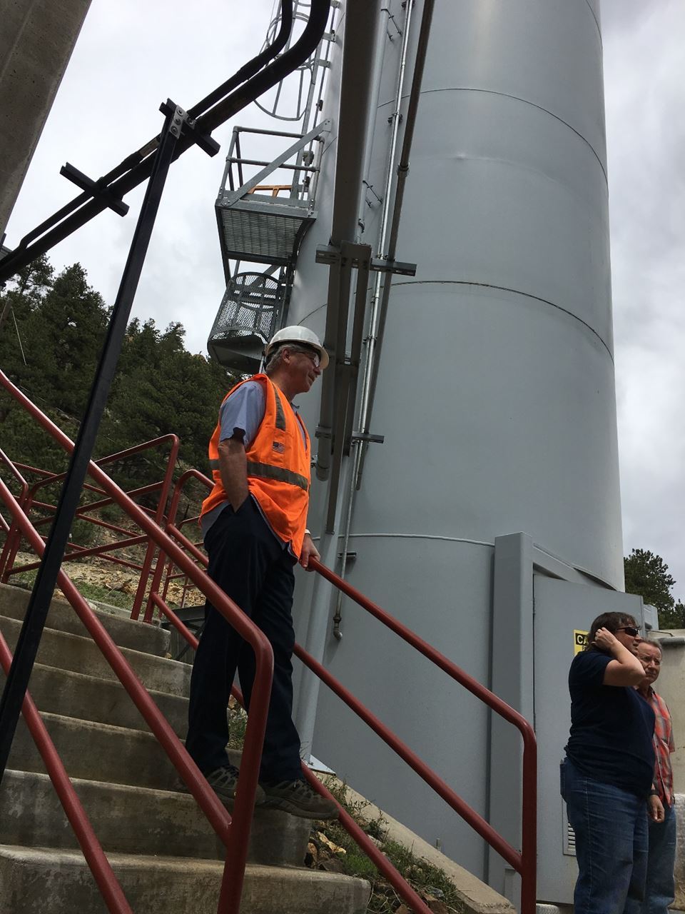
Figure 5: Equilibration basin Figure 6: Lime storage silo
This mixture is sent to a sludge thickener where the precipitates settle by the force of gravity from the water, and the clarified water flows off the top. A polymer (Figure 7) is added in a low dose to improve settling and filtration performance. The overflow water is polished using a sand filter, and then treated with hydrochloric acid to achieve a discharge pH of approximately 8.5 S.U. (Figure 8). The precipitates are pumped from the bottom of the sludge thickener and then sent to a plate-and-frame filter press. The solid filter cake contains approximately 35-40% solids and passes testing of the Toxicity Characterization Leaching Procedure (TCLP), characterizing it as a nonhazardous waste and is disposed of in a municipal landfill.
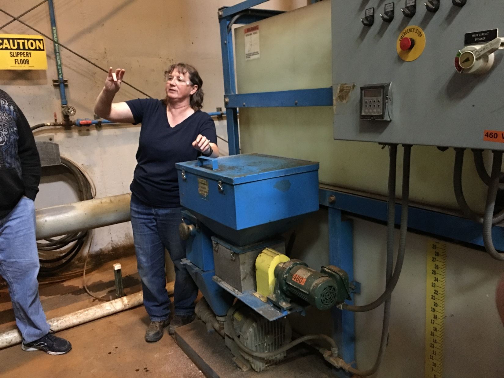
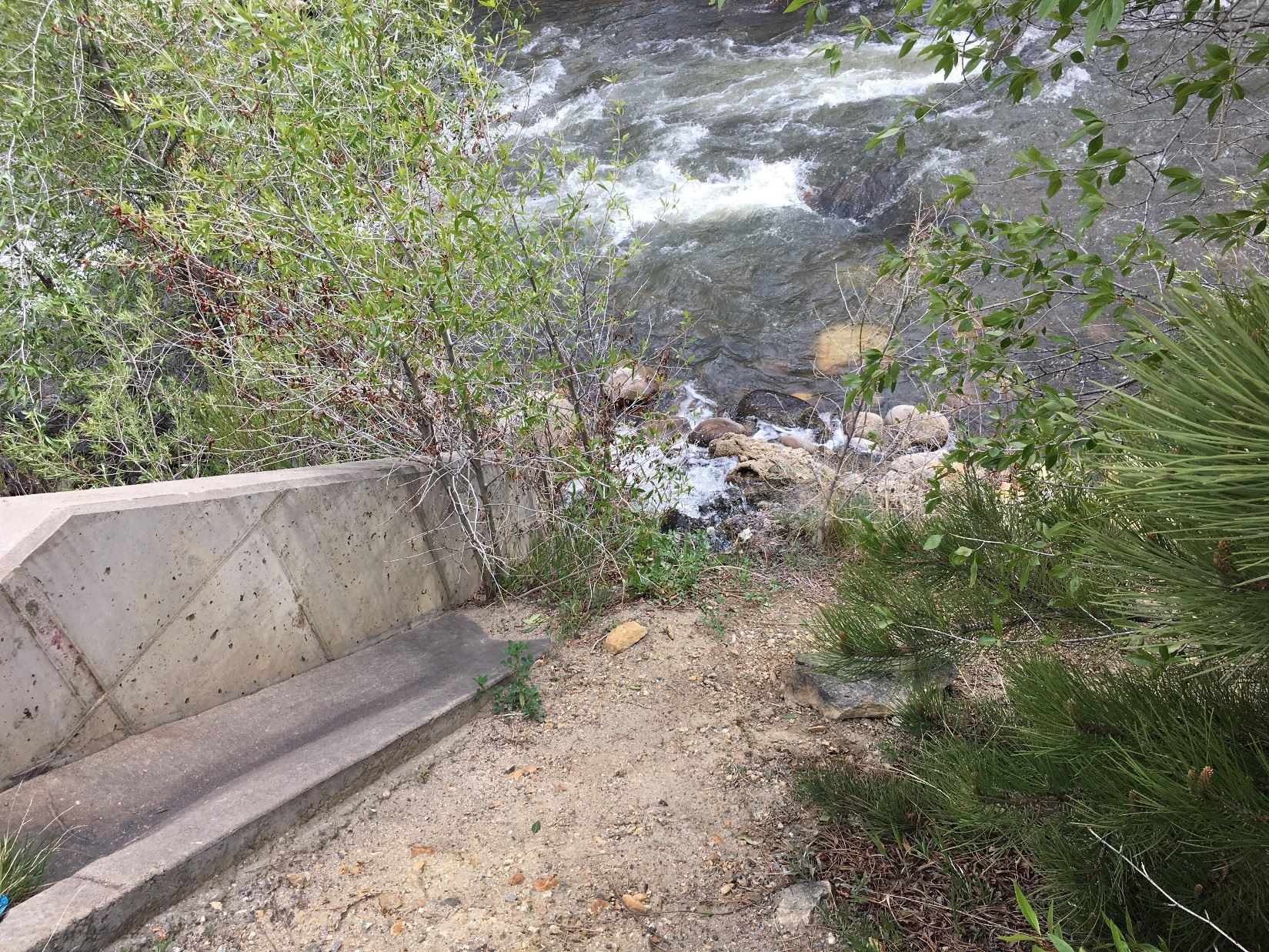
Figure 7: Mary Boardman showing polymer system Figure 8: Outfall
Special thanks to Mary Boardman with the Colorado Department of Public Health and the Environment for giving the RMWQAA group the tour!
Lindie Aragon is the Chemist at the City of Westminster's Wastewater Lab. She is the head of the RMWQAA scholarship committee and coordinated the Argo tour.